STM32F103 expansion board
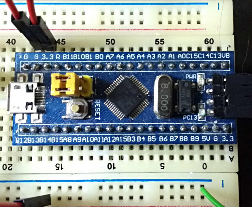
26 Jul 2017I've been using these little STM32F103C8 based modules in most of my electronics projects. They’ve got a full ARM Cortex-m3 core, 20 KB of RAM, 64KB of Flash, lots of peripherals (I2C, UART, SPI, USB device, ADC, timers, RTC) and you can buy them on a board with crystals (8MHz and 32kHz) for less then £2/$2. You can find them on AliExpress by searching for stm32.
You do need a separate programmer, but you can find ‘unofficial’ ones online for only a little more then the boards themselves, and you only need one (and maybe a second, just in case).
There’s only one problem with them, which is once you’ve got them in a small breadboard there’s not much room around them to plug anything in, especially if you want to probe the outputs when talking to other components.
This felt like a good excuse to make another PCB as I haven’t done one in a while. While this used to be expensive since the online producers based in China appeared you can get ten 100x100mm boards made and sent to you for less then £14, so they’re not exactly expensive.
I started by coming up with some ideas for the design:
- Socket for the STM32F103C8 boards with all useful pins brought out.
- Easy connection of external modules using Dupont wires.
- Access to signals without having to stack cables.
- Choose between of either a mini breadboard (400 point, 85x55mm) or some SMD pads for connecting stuff.
Final design
Here’s the design that I came up with:
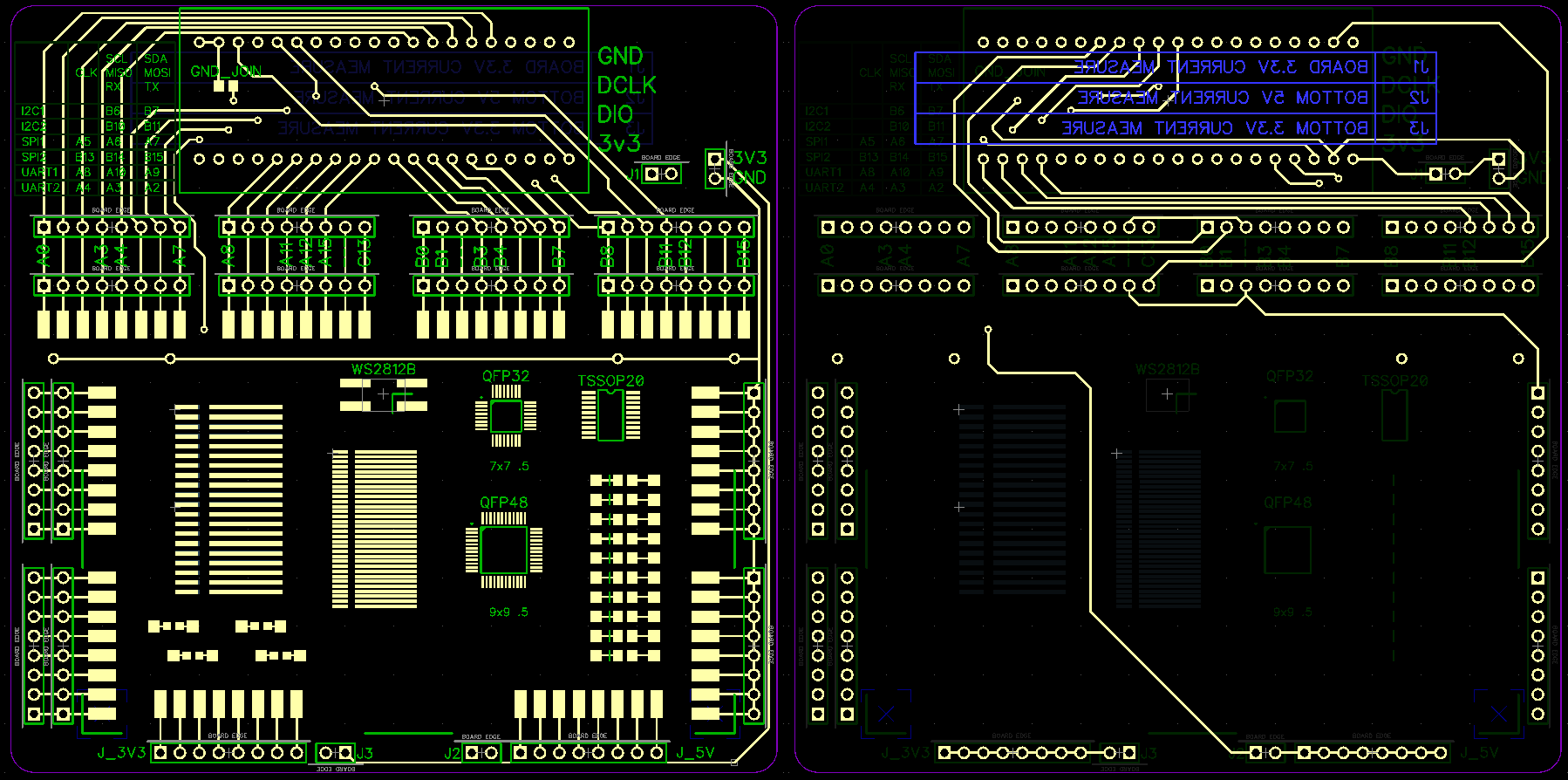
I'm not sure whether it’s best to use male or female headers on the board, but since they use the same footprint that’s something I can decide later. Female headers seem the simplest, as you can use the same male to male cables you use on the breadboards. That said, having one row of the I/O pins as male would make it easier to attach probes directly to them.
I'll do another post once the boards have turned up and I’ve built one up so you can see what they look like.
PCB production hints
Every time I do a PCB design I learn something, so I thought I’d go through the mistakes I’ve made to save you from making them as well.
Check your jellybean components really are
If you don’t know, jellybean components are generic ones where the exact version shouldn’t matter. E.g. a 3.3v voltage regulator, basic op-amp etc.
On my first board the ‘generic’ 3.3v regulator I found turned out to have a different footprint from almost every other manufacturer.
Preview your Gerber files in another viewer
This doesn’t just pick up errors in the software, or that you made in the export, but just gets you to look at them with something different. Sometimes just looking at the same thing with a different interface, colours or tool can make you notice something you missed. If your PCB tool doesn’t include it’s own viewer then you’ll probably be doing this anyway, but it doesn’t hurt to double check.
My second board had some manually drawn pads, I can’t remember why, and I forgot to remove the solder mask. This gave me perfectly placed pads that you couldn’t solder to. I ended up using a knife to scratch away the mask so I could get to the pads underneath.