I2S on the STM32F103
4 Oct 2017So I decided to try and make the cheap STM32F103 based boards I use do I2S, which was interesting as they’re not designed to do it, the main issues you hit are:
- Main PLL doesn’t support arbitrary clock division, only powers of two, this makes anything other than 32kHz impossible with good accuracy.
- No second PLL for generating auto bitrates, which limits the CPU speeds you have access to (e.g. multiples of 32kHz).
- No built in I2S support in the SPI module.
What’s I2S?
I2S is a standard used for audio in electronics. It’s basically SPI with an extra signal to keep track of which channel is being sent (called Word Select in the official documents and Left/Right elsewhere).
What you get is a clock, a stream of data bits, and the WS signal dividing it up. By sending the most significant bit (MSB) first it copes with longer or shorter bit lengths without the receiver caring. If it’s expecting 16 bits and get’s 32 it just ignores the last 16. On the other hand if it expects 32 bits and only gets 16 it just leaves the least significant ones at zero.
The only weird thing is the WS signal changes on the bit before the MSB is sent. This lets the receiver get ready to switch to the other channel after it’s stored the current bit, rather then having to store, switch and send onwards at the same time.

First problem: Generating WS
As the F103 doesn’t support I2S the SPI module doesn’t generate a WS signal for you, so we need to make our own. In order for everything to work it needs to be in sync with the clock and data of the SPI module, so doing this in software isn’t going to be possible if you want to be generating audio on the microcontroller as well.
The F103 has some hardware timers that let you do stuff like this, there’s some delay but it’s stable.
Timer setup
Unfortunately the ST documentation and STCube don’t make it clear exactly how to set this up, as we need to output a signal that changes every 16 ticks of the SPI clock, which we can’t get directly inside the micro.
Each timer has 4 channels, that share a common master clock source and some other bits. The channel’s input stage has filtering and edge detecting, while the output stage has a pre-scaler and counter unit.
In the simplest mode the counter just increases until it hits a configure value where it raises an interrupt. However you can configure them to count the number of ticks between edges (to measure the width of pulses), or to change the state of the output pin based on a comparison with another value. By setting these you can create a PWM output that runs completely in hardware.
While the channels are separate they are partly linked, so you can have channel 1 as an input, filtering on rising edges and using that value to trigger channel 2, which is what I ended up doing.
So the setup I used goes like this:
- Channel 1: Input: Falling edge, no filtering.
- Channel 2: Counter: Clock source is Channel 1 (called TI1 in cube), set to count up and reset on 31.
- Channel 2: Output: PWM, pulse set to 16.
By connecting the SPI clock to TIM2_CH1, TIM2_CH2 outputs a signal that toggles every 16 bits.
To get the early switching, as I2S requires it to change on the bit before, I start the counter from 1 instead of 0. This does make the first word slightly shorter, but this isn’t an issue as described earlier. Now this could double the first value sent, but if you start with a silence buffer (all 0’s) anyway it’s not a problem.
Audio streaming
That’s the clocks sorted out, now for the data. I2S on STMF407 lets you start the next write in the TX complete interrupt and everything carries on without missing a bit. So you can have two buffers and write to one while other is being sent, then switch around when you get the finished interrupt.
This doesn’t happen on the F103. Even if you start the next write in the interrupt handler it ends the current SPI transmission and you have to wait a few clocks for it to reset and start again. As the output frequency is directly linked to the bit-rate this wouldn’t sound very good.
The solution is to switch the DMA controller to circular mode, which to be honest might be the better way of doing it on the F407 as well. Doing this transfers the whole buffer to the device, then starts again at the beginning.
This stops the pausing issue but creates another. You need to always be writing ahead of the DMA controller, but not so far ahead that you catch up and over-write what’s being sent.
Luckily there’s two DMA interrupts, one that fires at the end of the buffer, and another the fires when 50% has been sent. So instead of two buffers you just create one and tell the DMA controller to send it forever and fill the half that’s just been sent when you get the appropriate interrupt. When you get the half-sent interrupt, you can re-fill the first half of the buffer, and on the complete interrupt fill the second half.
So it works?
Almost.
About 50% of the time it starts and you get the correct signal, the other 50% you get a noisy distorted version of the sound. Looking at the output on my scope it’s clear what’s going wrong, the data is getting shifted by a bit or two causing it to wrap around (as it’s two-compliment integer values) and distort. The annoying thing is, it’s almost 100% reliable when I’ve got probes on the data lines, which makes debugging slightly tricky.
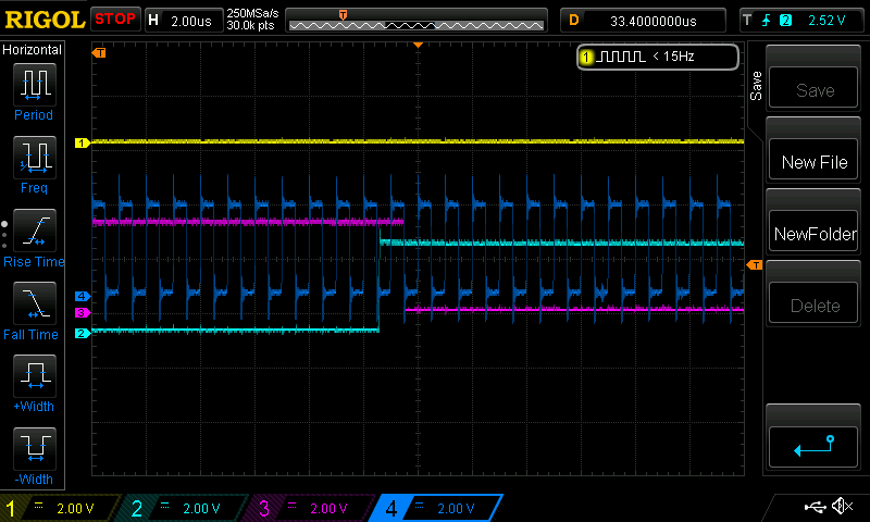
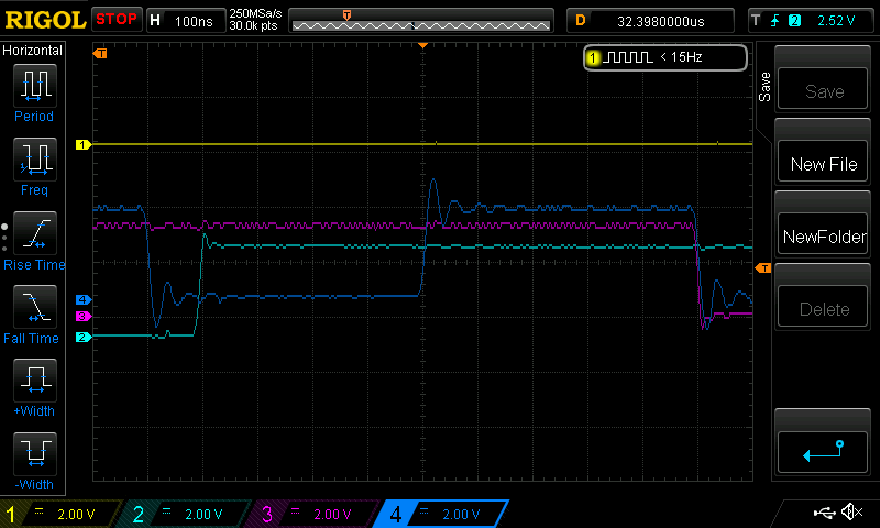
I'm guessing the extra load caused by the probes is slowing the rise/fall times enough to keep things happy.